
Tutorials Menu
How to Draw Shadow Diagrams >>>
How to Draw Shadow Diagrams in Elevation >>>
How to Draw Shadow Diagrams on Sloping Hilly Site >>>
How to Draw Shadow Diagrams >>>
How to Draw Shadow Diagrams in Elevation >>>
How to Draw Shadow Diagrams on Sloping Hilly Site >>>
How to Draw Shadow Diagrams on Sloping and Hilly Sites in 2D
| This 2D shadow diagram tutorial will explain how to manually work out shadow diagrams for sloping and hilly sites. In the example used, all the wall heights are determined based on height from ground level to top of wall.. After the initial shadow diagram is created, we can then go onto working out the additional shadow lengths for the sloping site. In Fig.1 below, the wall heights above ground level have been noted, and the contours are at 1m fall intervals. 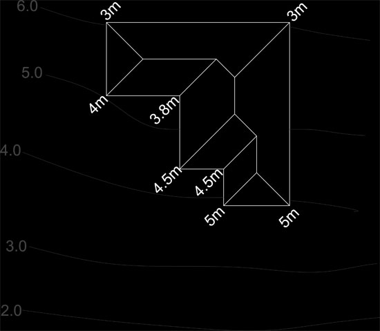 Fig. 1 - Wall Heights above natural ground level Now generate the shadow lines for the time you want using the wall heights above ground level. We need to draw a section to see what the additional length of the shadow will be. First measure the distance between the wall and the shadow line extent. Fig.2 below shows the horizontal dimension of the shadow lines. 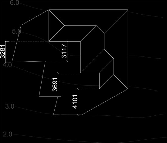 Fig. 2 - Shadow lines generated based on Fig.1 heights. Once you have noted the horizontal dimensions of the shadow lines, we can now prepare a basic section to determine the additional length of the shadow lines for the sloping site. Fig.3 below shows a section using one of the horizontal dimensions of the shadow lines from Fig.2 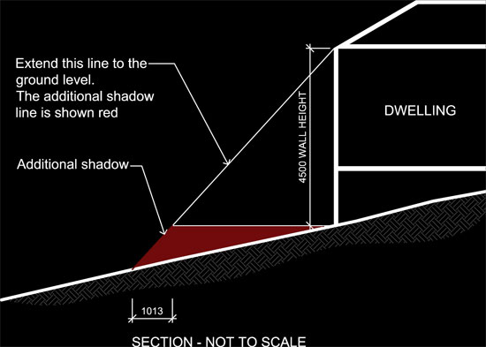 Fig.3 Section showing additional shadow length. In the section, I have drawn the approximate ground level and height of wall at that point. As you can see in the red area, the additional horizontal line of the shadow line is 1013mm. So, based on that, we can move the horizontal shadow line South 1013 to show the extent of the shadow line. 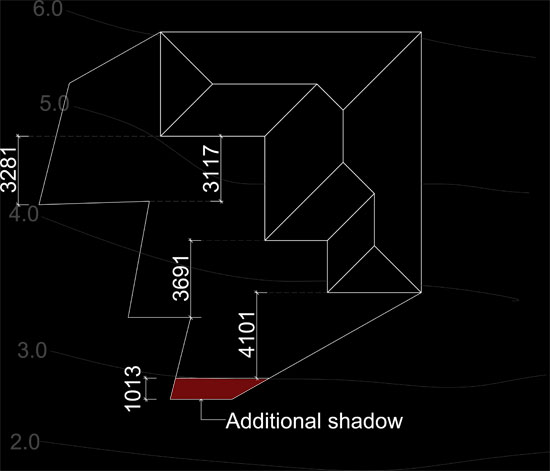 Fig.4 Shows the additional shadow line added 1013mm South This is how you can calculate the shadow diagrams for a sloping sites/hills. It isn't as accurate as a 3D model, but with some care and attention, you can calculate the shadow diagrams close to what they should be. In this case the shadows developed for sloping sites gives a general guide only and a 3D model (especially for complex slopes) should be used to create the shadow diagrams. You also need to work out the horizontal dimensions for the other side of the buildings shadow lines as shown below in Fig.5. 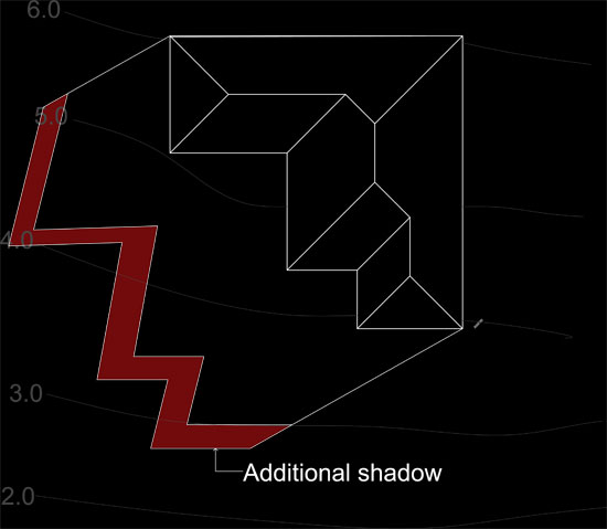 Fig.5 Red shows additonal shadow lengths for sloping site. |