How to Draw Shadow Diagrams on Sloping and Hilly Sites in 2D
This tutorial will explain how to draw shadow diagrams in elevation or section view.
You can download the PDF guide here
Shadow Diagrams are often just shown in plan view to see the potential overshadowing. May impact neighbouring properties. This type of shadow diagram sometimes does not give enough information to how high up a window the shadow will cast.
At times councils request additional information to see how the shadow from the proposed building works will cast up a vertical surface on the neighbouring property, usually to see how the shadow may affect habitable room windows.
There is a lot of misunderstanding to how to prepare this type of shadow diagram in elevation / section view, as well as guides that are just completely incorrect.
In this guide you will learn how to prepare this type of shadow diagram correctly
Step 1
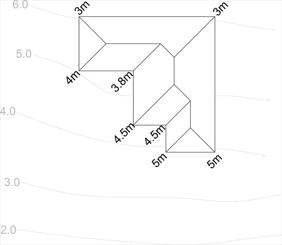
Fig. 1 – Wall Heights above natural ground level
Now generate the shadow lines for the time you want using the wall heights above ground level.
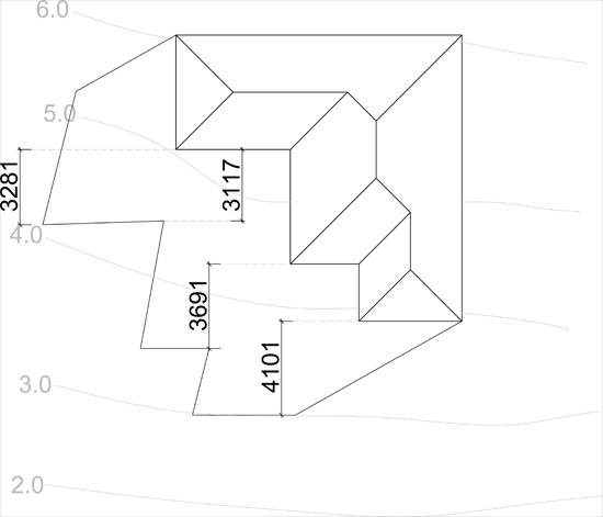
We need to draw a section to see what the additional length of the shadow will be. First measure the distance between the wall and the shadow line extent. Fig.2 below shows the horizontal dimension of the shadow lines.
Fig.1
Step 2
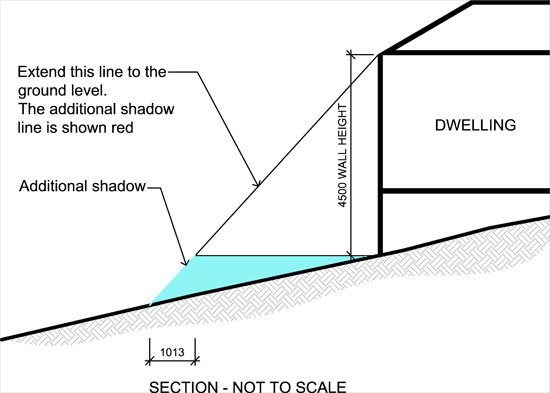
Once you have noted the horizontal dimensions of the shadow lines, we can now prepare a basic section to determine the additional length of the shadow lines for the sloping site. Fig.3 below shows a section using one of the horizontal dimensions of the shadow lines from Fig.2
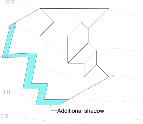
Fig. 2 - Shadow lines generated based on Fig.1 heights.
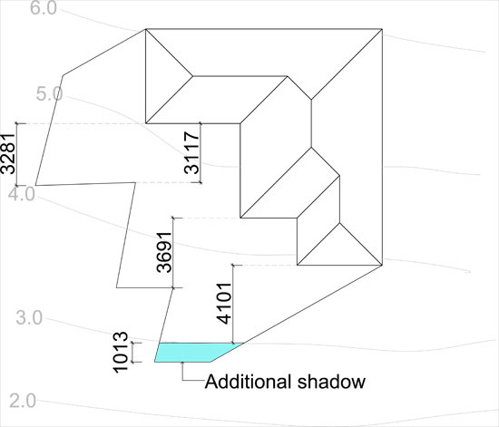
Step 3
In the section, I have drawn the approximate ground level and height of wall at that point. As you can see in the red area, the additional horizontal line of the shadow line is 1013mm. So, based on that, we can move the horizontal shadow line South 1013 to show the extent of the shadow line.
Fig.3 Section showing additional shadow length.
Step 4
Fig.4 Shows the additional shadow line added 1013mm South This is how you can calculate the shadow diagrams for a sloping sites/hills. It isn’t as accurate as a 3D model, but with some care and attention, you can calculate the shadow diagrams close to what they should be. In this case the shadows developed for sloping sites gives a general guide only and a 3D model (especially for complex slopes) should be used to create the shadow diagrams. You also need to work out the horizontal dimensions for the other side of the buildings shadow lines as shown below in Fig.5.
Fig.4
Step 5
Fig.5 Blue shows additonal shadow lengths for sloping site.
Fig.5